Add Your Photos
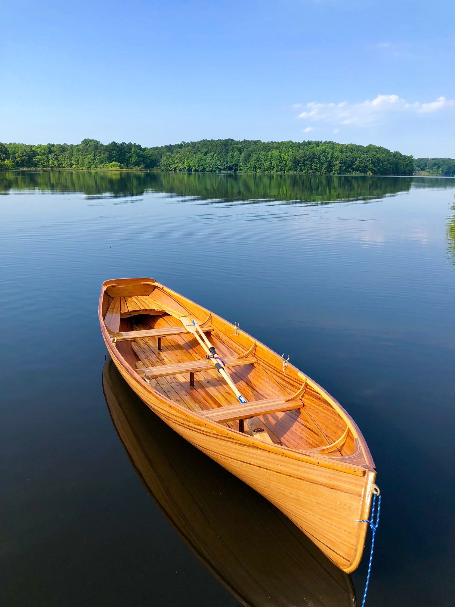
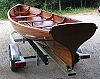
June 11, 2018 - We took it out for a spin last weekend for the first time after starting the build last Thanksgiving. Best time I’ve ever had on a rowboat! I caught myself rowing too slowly several times because I couldn’t get used to the way this boat maintains speed between strokes.
2 Photos
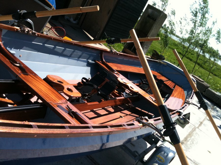
February 2015 - These pictures show the Whitehall I build some years ago for a customer, who wanted to row sportly. It was straightforward boatbuilding with a sliding benches frame that could be taken out and outriggers that could be taken inward for moonlight rowing. I used the Glen-L Sliding Seats plans to build the 2 rowing seats, which make this a unique boat.
6 Photos
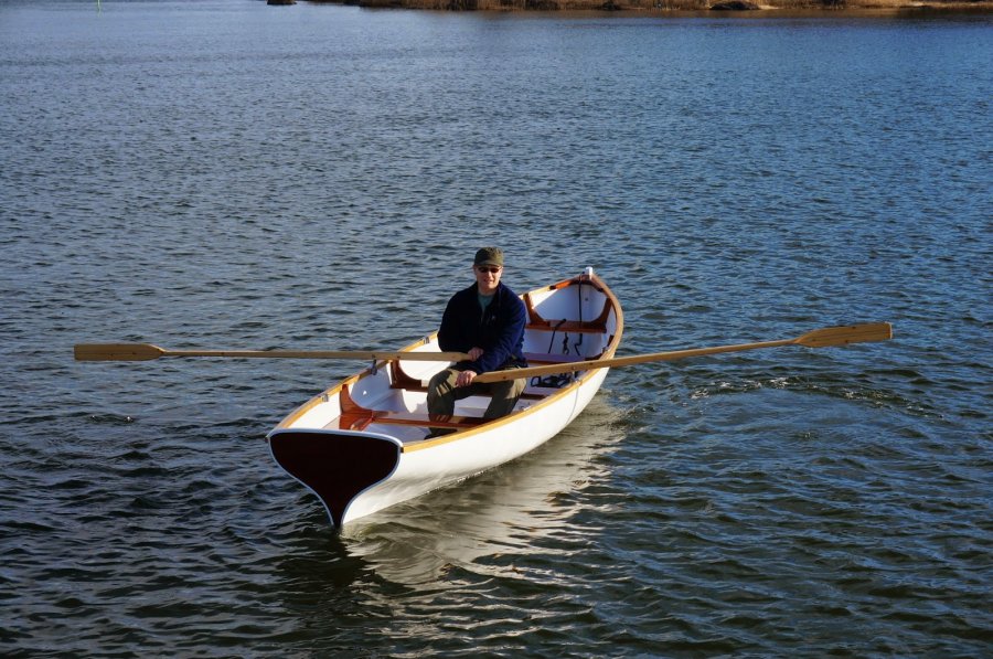
Update June 2014 - July 2012 - Please visit my complete blog of my Whitehall build at http://splinterinthefinger.blogspot.com/
45 Photos
Boat building is for me a therapeutic pastime and I built an electric launch based on the Whitehall design. My reasoning was that these launches not only have lovely classic lines but are, by virtue of their development as harbour taxis in a competitive environment, very efficient and stable hulls. I reasoned that a launch that could be rowed at or near hull speed by two rowers would be easily driven bij an 80 pound Minn Kota which was/is the largest commercial (ie affordable) series built drive head available. I built the launch with a strengthened hull and stern so that I could hang a rudder with the drive unit built in off the stern. I located the 4 semi traction lead cells in the middle and located the drive control and main switch next to them in the central rowing seat. To give some compensating flotation I enclosed the fore and aft decks. The result is an electric launch which runs very quietly, at a reasonable price and surprisingly stable due to the 120 Kg batteries low in the centre of the boat. It happily cruises for 6-8 hours at around 5 knots, just under hull speed, which is also the nominal motor speed. Scares the hell out of ducks who don\'t hear it coming... The best way to cruise it is to chuck in a few bean bags and lounge on the floor within reach of the motor controller and a hand on the tiller extension. To improve steering at low speed I later added a rudder blade built around the motor and a cap rail. I thought you might like to see this variation on your design. Launches are quite popular in the Netherlands, but most are too heavy to trailer and launch comfortably for a day\'s outing. This one will launch easily in 10-15 minutes so you can cruise wherever you like in different areas and avoid the cost of keeping it at a mooring, like most launches here. Electric drives are becoming more popular as increasingly nature reserves are banning the use of petrol or diesel motors. I built the boat in 10X20 mm Gua Riuba strips, a good (FSC certified) alternative for teak with the same deep honey colour and very tough and strong. The whole boat is epoxy glued and edge nailed with stainless steel and the lower hull is strengthened with two layers of \'glass epoxy. The interior, floors and seats are in made Laurus, which keeps a good grip when wet and are only oiled for preservation. After 4 years of (light) use I have had virtually no maintenance to the hull and only a yearly oil rub for the laurus bits. Probably I would use a less tough wood for a next one: the 1/4 turns in the lower hull fore and aft all needed to be shaped with heat. I used a heat gun (paint stripper) for this, which I found quite effective. The drawings were great to work with: thought I would get CAD drawings but the blue prints or hand drawn work was a delight for this engineer! Thanks for great drawings and keep up the good work!
8 Photos
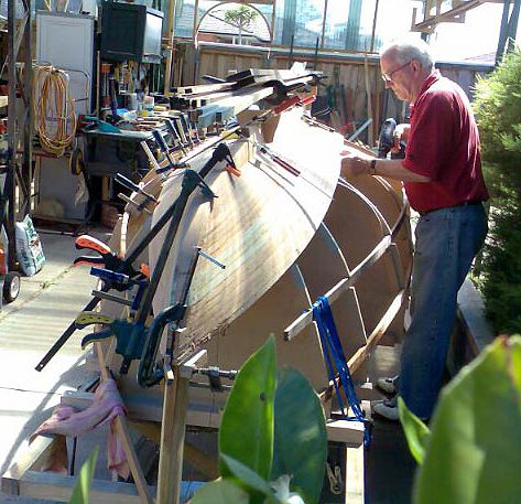
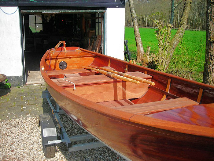
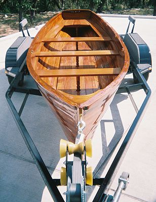
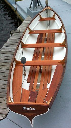
Early in 2004, I decided to pursue boat building as a fill in pastime, primarily for the downtime between our carpentry jobs. My wife Sue and I are finish carpenters, and especially during the winter months, find ourselves with time to kill. Having dealt with Glen-L back in the 70\'s while considering the building of the Klondike, they were the first place I checked for plans. Not wanting to jump into power boats right away, I was immediately drawn to the Whitehall; the lines are incredible, the size was appropriate for towing with practically any car, and with the multiple rowing stations, the possibility of longer boat rides with multiple persons to share the work seemed like an added benefit. I sent for the plans, looked them over for a day or so, and ordered 200 bd. Ft of 4/4 Philippine mahogany and a couple of 16 ft planks of 8/4 for the heavier parts. While this order was being processed, my usual supplier for building materials was delivering the 2\" x 6\" stock for the building jig. As I could see the possibility of building several of these boats (with appropriate payments to Glen-L), I built the support platform a little beefier than would normally be called for; lots of bolts, lags, and steel reinforcing. It took a day to build the form. As I was laying out the station molds directly on the forms top edges, much care was used to square the form. Two x 2\'s across the top of the form located all the molds. The transom was built exactly as drawn, as was the inner and outer stem. The stem pieces were laminated from mahogany. The keel was cut from one of the 8/4 planks, as were the floor timbers (a little waste there, but 6/4 wasn\'t available at the time). Keel bevels were taken at each mold with the keel just clamped into place, and test fit with a short piece of planking stock. The bevels at the transom, inner stem, thwart riser, and molds are a little testy. Because, in my case, it took 70 plank strips per side, and only half of these are full length, fairing everything at first was a little stressful. This issue was resolved with a cloth tape measure. Each mold, along with the stern and transom, were marked off with colored markers at roughly 3\" intervals. This allows some common points for fairing with long (18 ft.) batten strips. You know pretty closely where the planking is going to fall. One thing t would do differently if I could, I would grind the keel to floor timber bolts with opposing flats on the heads. Counter boring a carriage bolt exposed some of this 3/4\" hole when the keel was beveled per the plan. Grinding the bolt head would only require cutting a small mortise to sink the bolt head in. This gives you a mortise 5/16\" w x 3/4\" long (the 3/4\" follows the keel centerline). The planking stock was cut from the 4/4 mahogany. I ripped it to a \"big\" 9/16\", and planed both edges slightly. Planning ahead, if the planking came out pretty smooth, not having to sand saw marks would speed up the inner/outer fairing work. The edges were bead and cove like a canoe plank joint. I worked with several radii, starting with just a radius (like maybe 1\"). Not good, due to the sharps turns at the aft end of the hull, too many open joints, either inside or outside depending on convex or concave hull shape. Ended up with a half round cove/bead cut. In theory and application this was pretty much the best way to go. Downside is on sharp turns in the planking, one or the other of the cove cuts sharp edges will get sanded off leaving a small crevice to be filled. The farther you get from flat plank to plank joint, the more of an issue this becomes. Still the best way to go. The cove and bead joints were cut on a Williams and Hussey molder. It could just as easily be done with router mounted in a LOOONG router table. Finished width on the planks was a bit over 5/8\". Possibly could go wider, but dramatic twists and turns would make installation needlessly tough. The installation of the planking was for the most part, pretty easy. The 5/8\" wide planking worked perfectly, except for a couple. When milling the plank stock I noticed one 11\" plank had a wind break about 4 ft. from the end, problem was I saw the break after a few strips were already cut. I missed them when presorting later. With the planking being so small, fastening options are few. I chose an 18 ga. brad nailer with 1 1/4\" galvanized brads. Worked well most of the time, except in the area of the thwart riser. One issue with any fastener is the nails have to go in straight, and often the planking is turning. End result is quite a few nails showing on the inside. Thought about clamps and wedges without nails, but the cove edge is fragile, the hull shape is radical in spots, and the huge forces required to maneuver the planks made this seem way to slow, considering the cure rate of the epoxy and the number of planks to install.
17 Photos
One Response to Whitehall Design
Connect with us:


Recommended:


[…] To see other builder photos and details, see the Whitehall Galleries here. […]